We repaired a confining-oil leak in our GDS ETAS triaxial cell by replacing two internal load-cell O-rings. After reassembly, a 20 MPa confining-pressure test showed no visible oil leakage. This illustrated record preserves the repair procedure for future use in our research group.
The repair concerns our 64 MPa balanced-ram ETAS cell with a 100 kN internal load cell. It describes this assembly and the guidance we received from GDS, rather than a general disassembly procedure for every ETAS configuration. Work on pressure equipment should be carried out by trained personnel, with the system cooled, unloaded, isolated and fully depressurized before opening any connection.
1 Finding the leak
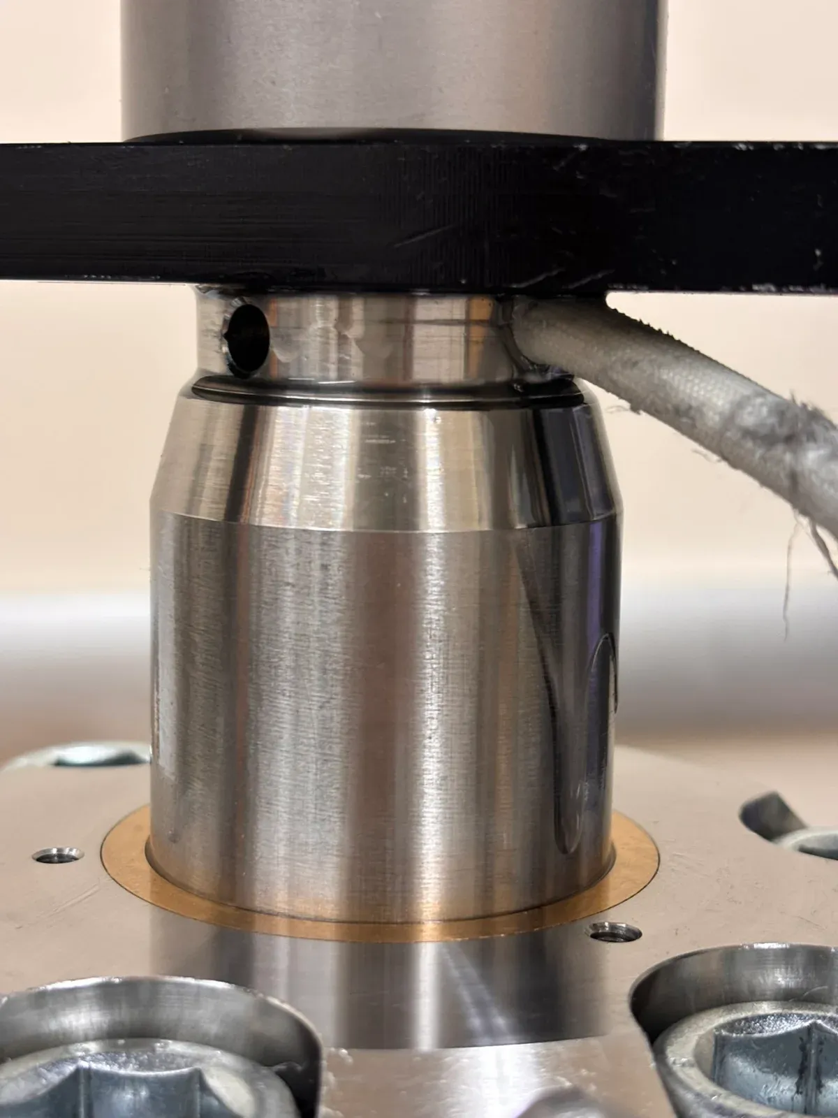
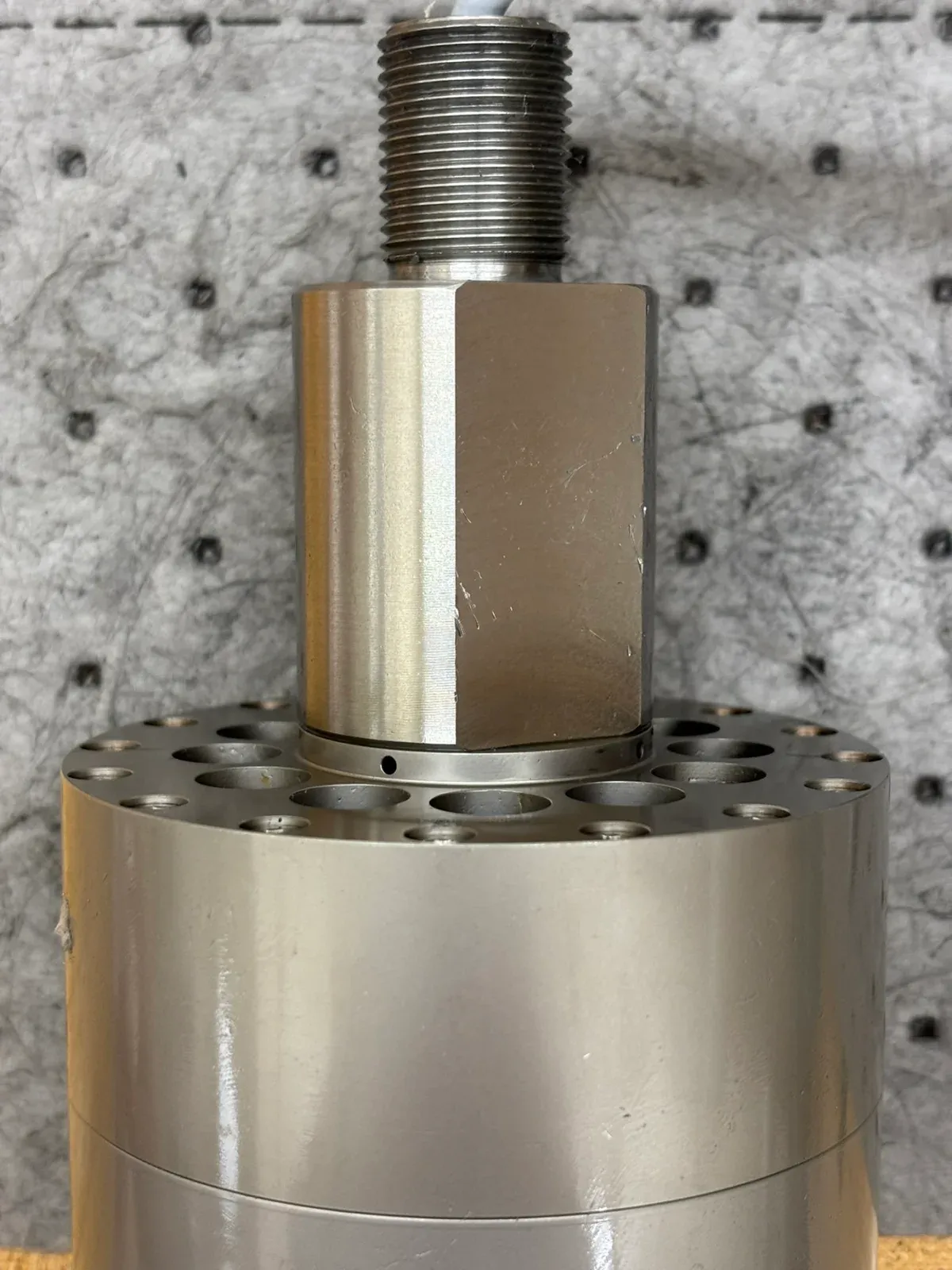
Oil initially appeared near the upper ram and top housing. Cleaning the external seal housing and adding grease did not resolve the problem. Closer inspection showed oil emerging from the opening where the load-cell cable exits the ram, rather than from the sliding ram interface (Figure 1).
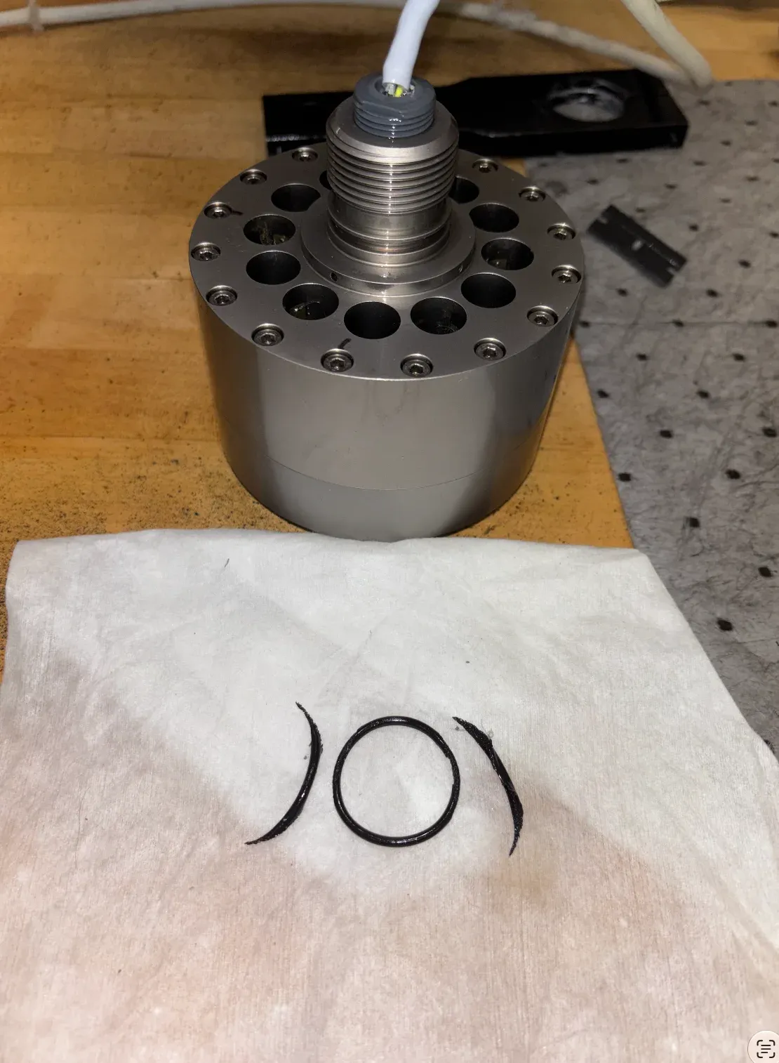
GDS directed us to two static O-rings inside the ram and load-cell connection. Once the assembly was opened, the seal at position 2 was visibly damaged and came out in three pieces: a remaining circular portion and two detached crescent-shaped strips (Figure 2).
The disappearance of the visible leak after replacement supports the internal-seal diagnosis.
2 Understanding the assembly
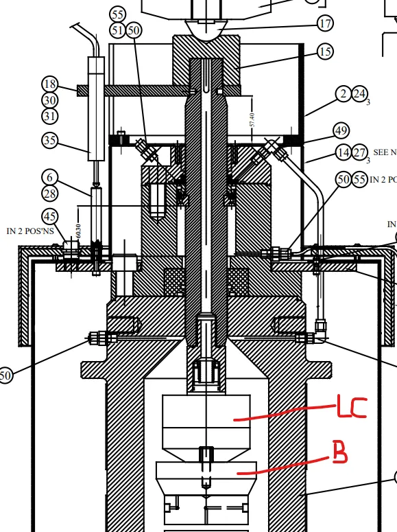
The load frame applies axial force through the ram to the internal load cell (LC), then through the brass extension cap (B) to the specimen. The specimen sits inside the pressure cell and is surrounded by confining oil. The upper balancing chamber is hydraulically connected to the main cell to reduce the net pressure thrust on the ram.
The load-cell cable passes through the hollow ram and adapter before exiting near the upper end. Two internal static seals help isolate this cable passage from the pressurized oil. The external sliding ram seals in the top housing form a separate seal system.
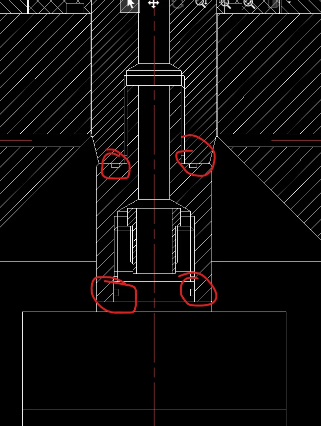
Figure 3 identifies LC, B and the upper components removed to free the cable. Figure 4 shows the two sealing positions.
3 Replacement O-rings
There are two specified internal O-rings in this repair, not two O-rings in the entire machine. Other cell joints and the external ram housing contain additional seals.
| Position | Location and function |
|---|---|
| 1 | Static end-face seal at the bottom of the ram, compressed when the LC assembly is seated. |
| 2 | Static radial seal between the load-cell connection and the internal adapter. This was the visibly damaged seal. |
GDS confirmed the same replacement specification for both positions:
| Specification | Required value |
|---|---|
| Quantity | 2 O-rings, one at each position |
| Material | Viton / FKM |
| Hardness | 75 Shore A |
| Inside diameter | 27.6 mm |
| Cross-section | 2.4 mm |
Use the specified material, size and hardness. GDS advised against standard NBR seals for this high-temperature system.
4 Tools and supplies
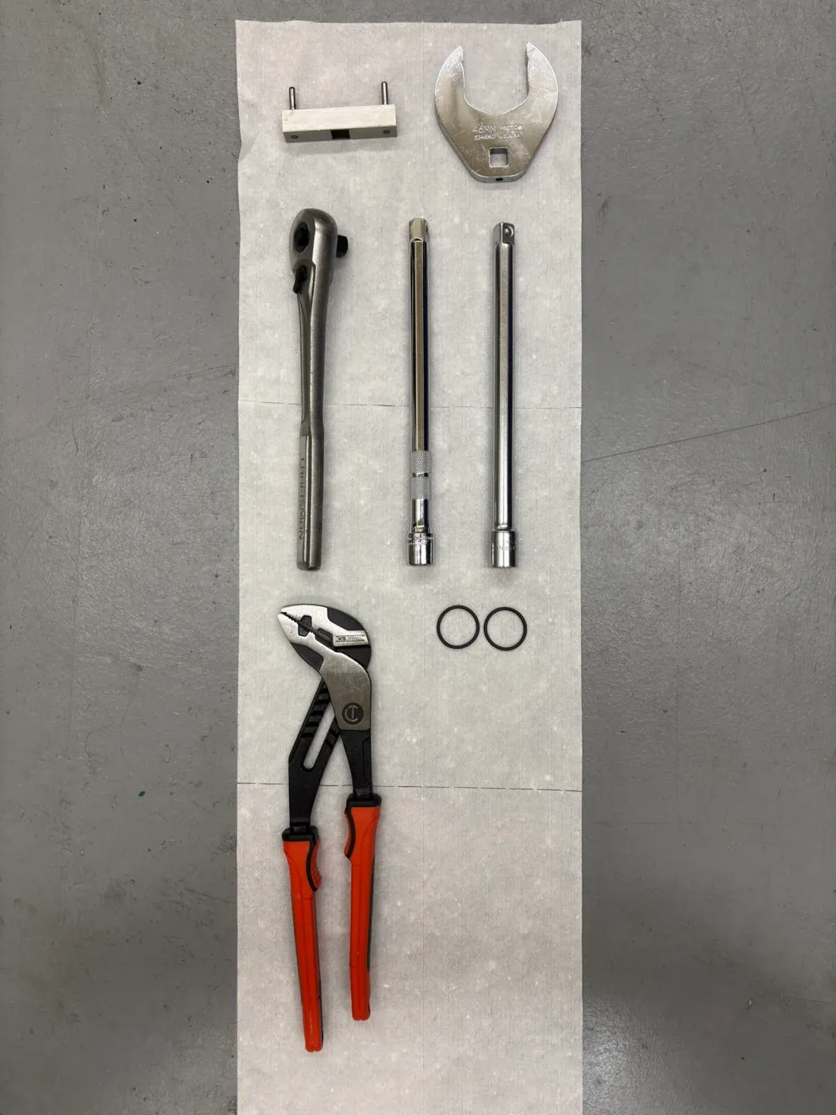
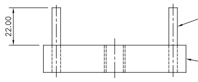
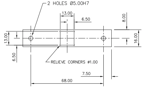
The tools used are shown in Figure 5. The face-spanner drawings in Figures 6 and 7 provide the fit details if the original tool cannot be found.
| Tool or supply | Purpose |
|---|---|
| 46 mm crowfoot wrench | Engages the two opposing flats on brass cap B. GDS confirmed 46 mm across the flats. |
| Original two-pin face spanner | Engages the two holes in the LC face. |
| Ratchet and long extensions | Reach the load cell from inside the pressure cell. |
| Well-fitting jaw tool or spanner | Counter-holds the central adapter while the LC is rotated. |
| Two new specified FKM O-rings | Replace both internal seals. |
| Lint-free wipes and a plastic seal pick | Clean the grooves and remove old seals without scratching them. |
| Secure supports and a second person | Support the heavy cell and removed parts. |
4.1 Face spanner fit
The drawing shows 68 mm between the pin centres, 22 mm pin projection, and a 13 mm square drive opening, nominally compatible with a 1/2-inch drive. Confirm a positive fit on the actual tool before applying force.
5 Repair procedure
5.1 Prepare access and free the cable
Remove the displacement-transducer bracket and upper ram cap identified by GDS as items 15 and 18 (Figure 3). Release the external cable restraints so the cable can follow the LC as it rotates. The cable is attached to the load cell; leaving it restrained can twist or stretch it.
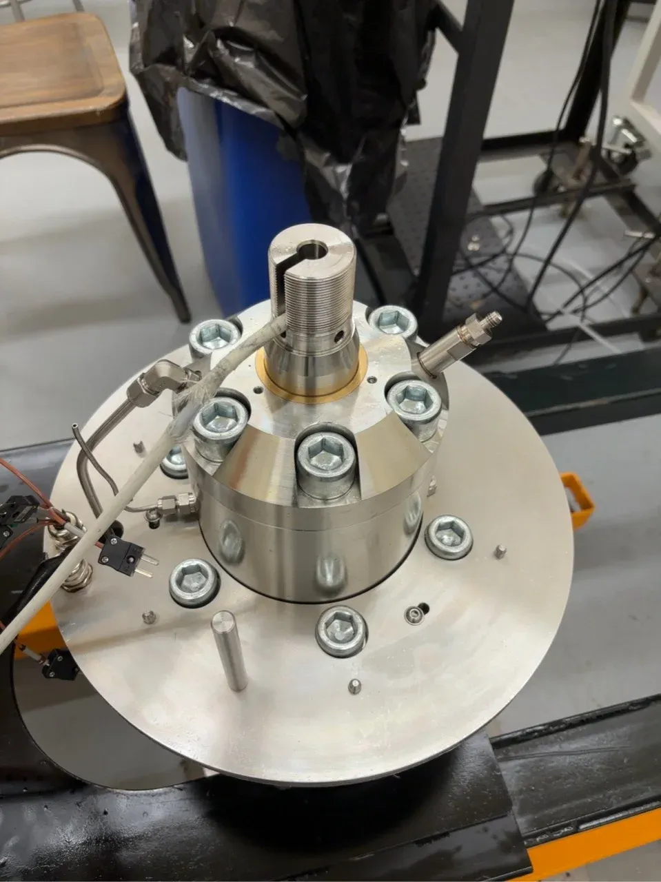
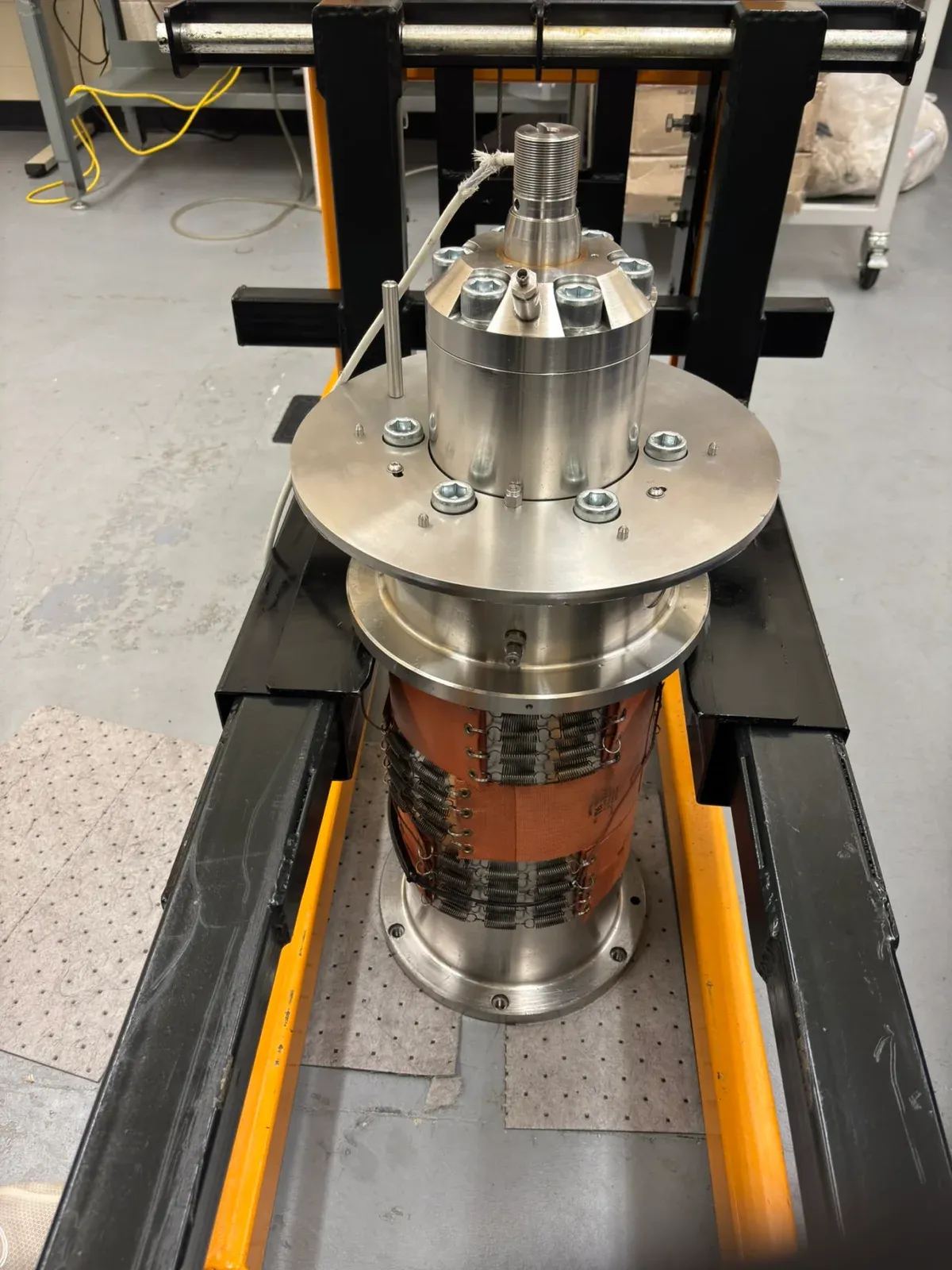
Figure 8 shows the upper components removed. Figure 9 shows the cell on its support frame before repositioning. GDS advised using at least two people to tip the cell and resting it on the metal shoulder or plate supporting the heat jacket. Secure it against rolling, and do not put its weight on heating pads, hydraulic tubing, connectors or cables.
5.2 Remove cap B and the LC assembly
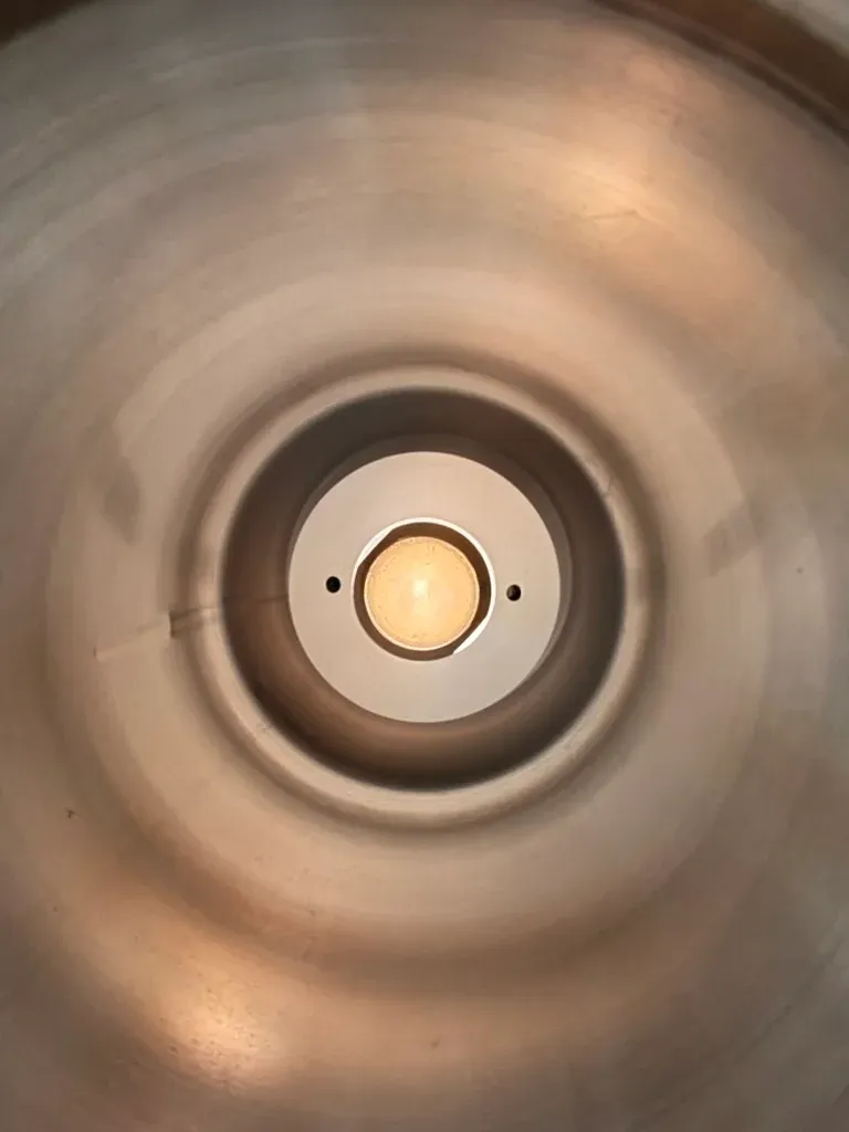
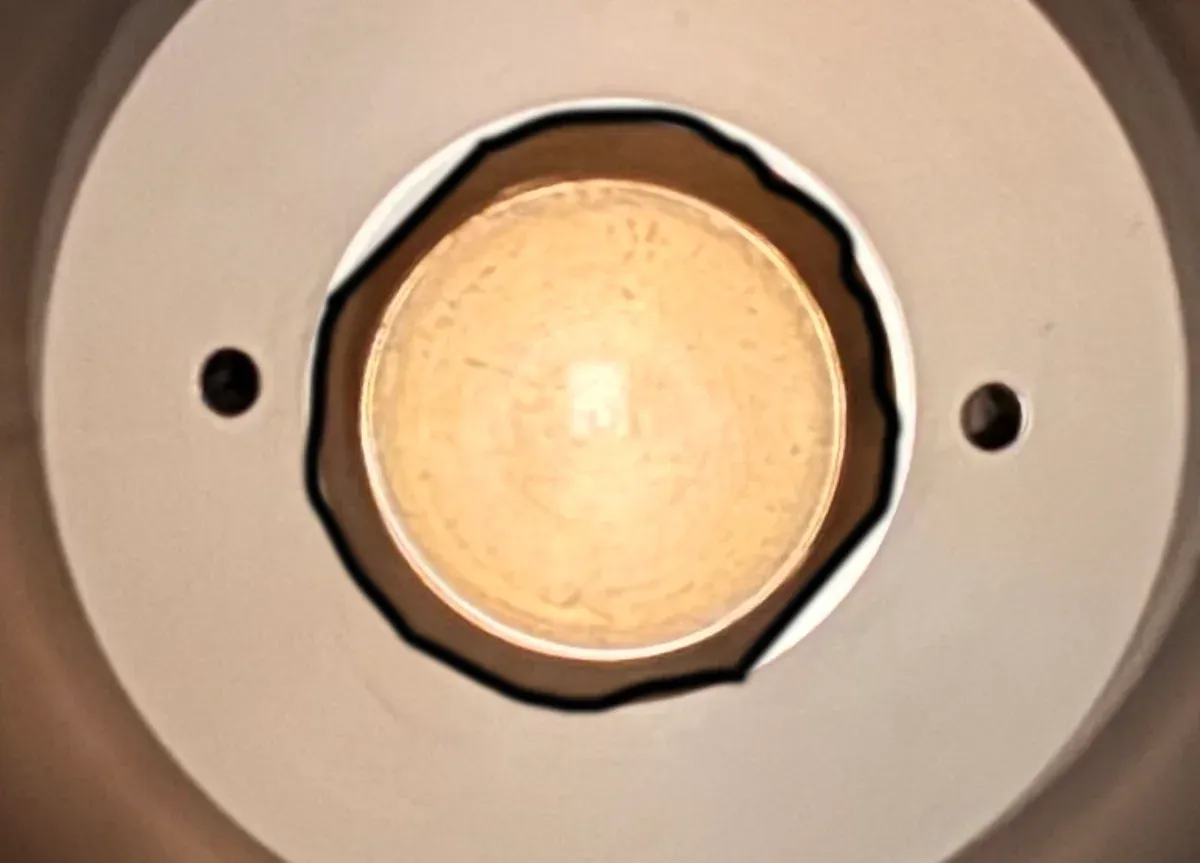
Access cap B from the specimen side of the cell (Figures 10 and 11). Seat the 46 mm crowfoot fully on both flats. GDS confirmed standard right-hand threads: viewed directly from the bottom face, counter-clockwise loosens and clockwise tightens. GDS does not use thread-locking sealant on B; once the initial connection is released, it should normally unscrew by hand.
If the LC turns with B, stop and establish a suitable counter-hold before continuing. Watch the cable throughout the operation; do not use it to resist rotation.
After removing B, engage both pins of the face spanner fully in the LC face holes. Unscrew the LC assembly using the GDS thread-direction guidance, support its weight, and withdraw it along the axis when the threads disengage.
5.3 Separate the LC and internal adapter
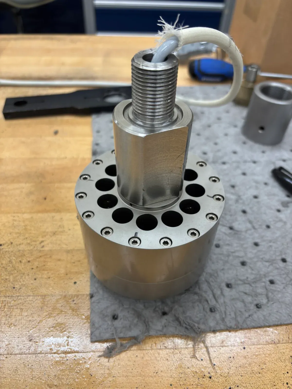
Removing the assembly from the ram does not expose position 2 by itself. The central adapter remains screwed into the LC, covering the side seal (Figures 12 and 13).
We separated this connection on a supported bench by holding the intended flats on the central component with the jaw tool shown in Figure 5, then rotating the LC with the two-pin face spanner. Keep both components supported and the cable free as the connection is released.
Use the intended flats for the counter-hold, rather than gripping a sealing surface, thread or cable. If the tool slips or the parts do not release under controlled force, stop and obtain further guidance from GDS.
5.4 Replace both seals
- Identify the end-face seal at position 1 and the side seal at position 2 using Figure 4.
- Remove the old rings and any detached fragments without scratching the grooves or bores. Clean the contact surfaces with lint-free material and keep debris out of the cable passage.
- Check that both replacement rings are FKM, 75 Shore A, 27.6 mm ID × 2.4 mm cross-section. Seat each ring in its correct groove without twisting it.
- Align the LC and adapter axially and start the threaded connection by hand. Check that the side ring is not pinched as the parts come together.
Both rings were replaced in the successful repair.
5.5 Reassemble and check for leaks
Seat the new position 1 ring before returning the LC assembly to the ram. Support the assembly, start the threads by hand, and keep the cable free while using the face spanner and extension. Follow the GDS tightening instructions for the specific joint being assembled.
Reinstall cap B, the upper ram cap and the displacement-transducer bracket. Restore the cable routing and hydraulic connections, then inspect the assembly before pressurizing it under the lab’s approved operating procedure.
After reassembly, carry out a controlled confining-pressure leak check.
6 Earlier inspection photographs
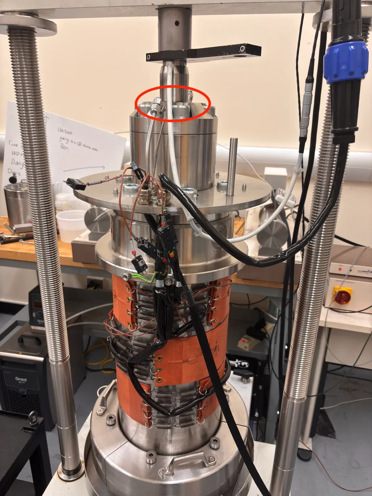
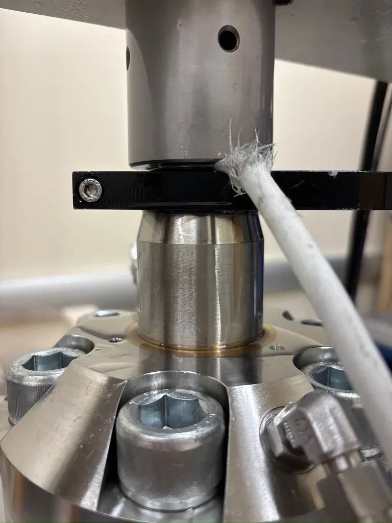
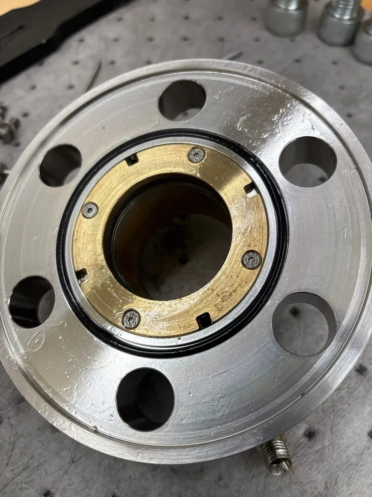
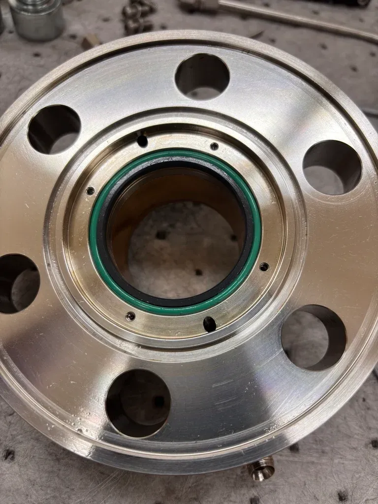
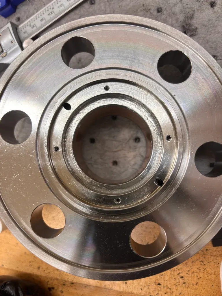
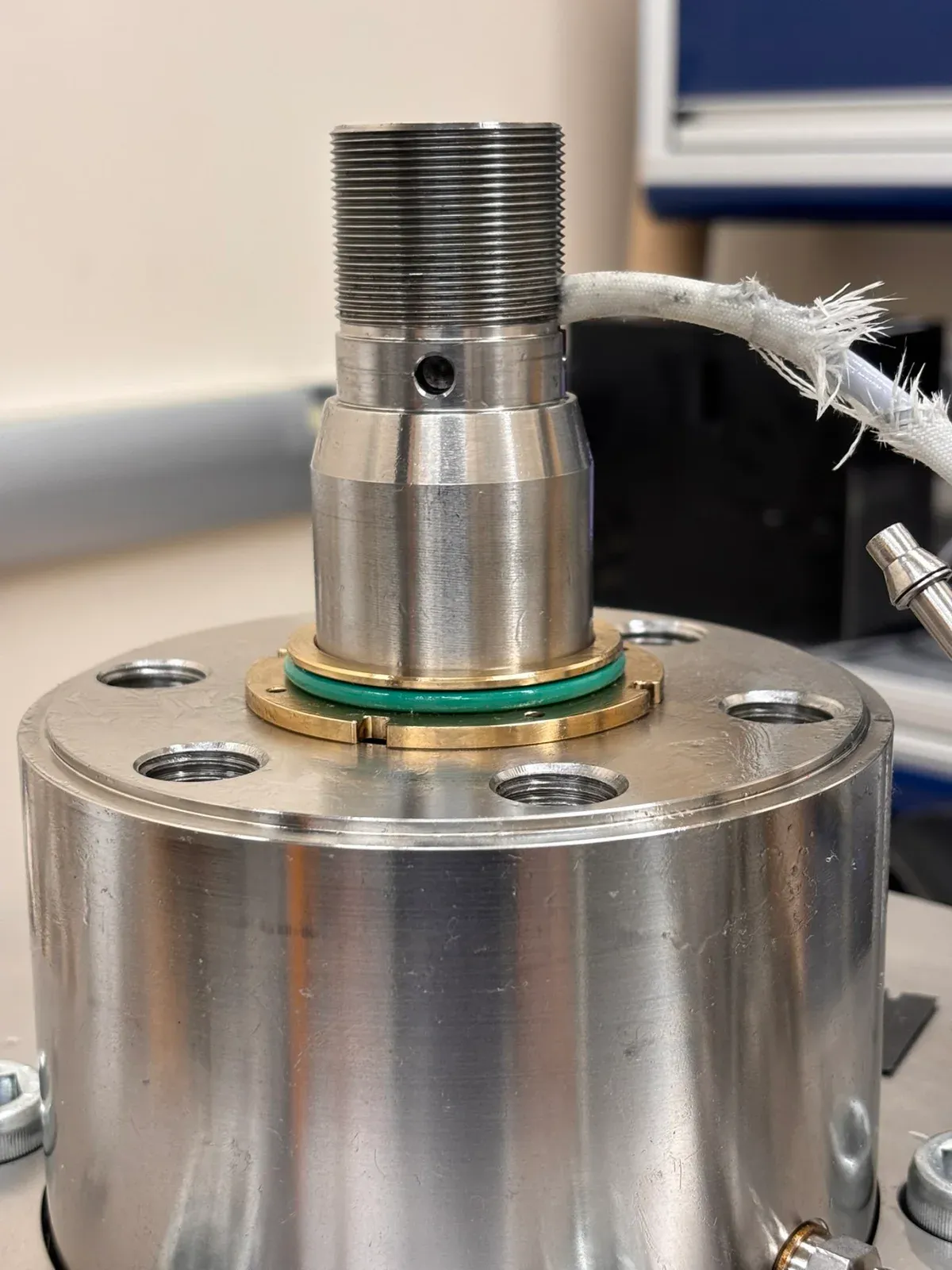
The initial investigation focused on the external top-housing seal pack. Figures 14–20 preserve that inspection for reference. These are not the two internal LC seals replaced in the final repair.
View the earlier top-housing inspection photos (Figures 14–20)

7 References and acknowledgments
The component identification, replacement-ring specification and access guidance came from GDS technical support during this repair. Sectional and tool drawings are supplied by GDS; the photographs document our lab work. Thank you to the GDS support team and our research group for helping us complete the repair.
- GDS technical support
- GDS ETAS product information
- Replacement-ring reference: FKM 75 Shore A, 27.6 mm ID × 2.4 mm cross-section
AI assistance: The wording and organization of this page were polished with OpenAI GPT-6.1 Sol in Codex. The repair details and test results are based on our laboratory work and GDS guidance.